
NPT
NPT American National Standard Taper Pipe Threads per ANSI/ASME B1.20.1 are commonly used on high pressure solenoid valves. The maximum allowable pressure is dependent on size and connector material, but can be as high as 10,000 psi. It is therefore always prudent to investigate pressure capacities with the component manufacturers.
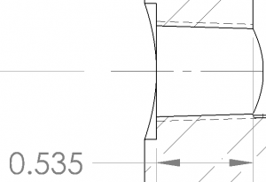
Picture 1 – ¼” NPT
Female NPT threads are created in valve bodies by tapping, single point turning, or thread milling. Unlike the SAE J1926 and Medium Pressure Connection, sealing is not created on interfacing smooth cone faces, but rather on the threads themselves. In order to provide good sealing across multiple brands of connectors, female connections should not only meet the “L1” gage distance per ASME B1.20.1, but also provide an adequate number of full threads past the hand tight engagement length.
Application of a thread sealant is mandatory in order to block the spiral path between the peaks and valleys of the male and female interface of ASME B1.20.1 NPT threads. Three to four wraps of PTFE tape is preferred over liquid sealants. This is because overuse of a liquid may cause drippage into operationally sensitive areas of the solenoid valve. Picture 2 is an example of how properly applied PTFE tape will look after a connector is removed from quality threads that have been fully tightened. The white tape is evenly compressed across the faces and valleys. One indication of improperly machined threads or inadequate length of engagement would be a thick string of PTFE nestled in the thread valley. This is one clue that the components did not (or could not) compress together fully.
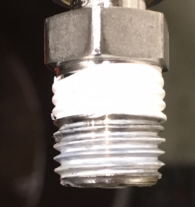
Picture 2 – Good application of PTFE tape
Installation torques are not commonly published for NPT connections. It is somewhat of a trial and error system to get them to seal by keeping track of the angle of rotation past hand tight. Reversing the connector out will ruin the sealant and will require the installer to re-apply. Consult the specification for the number of threads that should engage, hand tight, for a given NPT size.
NPT is the easiest connection to manufacture, and is sufficient for the bulk of solenoid valve applications. However, once an assembler gets the connection to seal, there is very limited flexibility on the angle of rotation to which it must connect to other things (e.g. piping, tubing, etc.) unless accommodations are made via adjustable tube connectors. There are also minor nuances between connectors from different manufactures.
SAE J1926
Connections per SAE J1926/1 utilize straight ISO 725 threads (inch) and a smooth 12 or 15 degree sealing cone interface. The male SAE connector has an o-ring of chosen material that seals on the female cone. The specification states a maximum allowable pressure of 63 MPa [9135 psi] for connections put together with nonadjustable stud ends, but always be sure to check with the component manufacturers.
As seen in Picture 3, the SAE connection is somewhat more elaborate than the NPT. For a comparable inner diameter through which fluid can flow, the connection tends to need more axial length in order to fit it into the valve body.
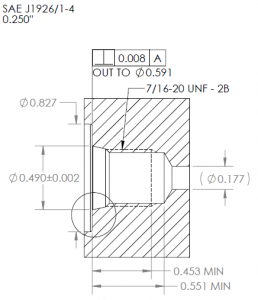
Picture 3 – SAE J1926-1 Size ‘-4’ Connection
From our experience at Clark Cooper it is easier to make a perfect seal with SAE connectors as compared to NPT. Installation torques are readily accessible for SAE. However, an end user must take the o-ring material selection into account to ensure compatibility with the fluid type and temperature. The SAE connection is generally not used for cryogenic applications due to that o-ring.
MPF
The 20,000 psi “Medium Pressure Fitting” (MPF) connection utilizes inch-based standard thread and a 60 degree cone at the base of that thread. All sealing is accomplished on the metal-to- metal cones without the use of an o-ring or thread sealant. This versatile connection, despite not requiring an elastomeric o-ring, can still perfectly seal high pressure gases such as hydrogen and helium.
Care must be taken during machining to ensure a smooth cone. Cleanliness is important as well during installation.
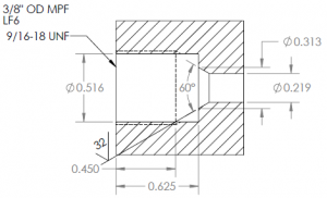
Picture 4 – LF6 Medium Pressure Connection