A solenoid, as it pertains to a valve, is an electromagnetic device consisting of a coil of insulated wire and an iron-based permeable plunger and pole piece. The following sequence demonstrates how such an arrangement can be utilized to make a plunger work to open or close a valve. Such is called a “solenoid valve”.
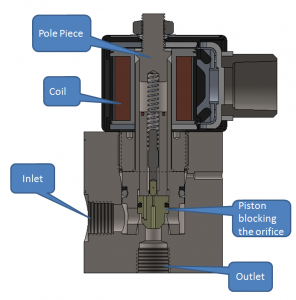
| Figure 1 is a section view of a piloted, floating piston, high pressure solenoid valve. Pressurized fluids enter at the inlet and are held stationary until the piston moves away from the orifice.
A coil is shown surrounding a pole piece outside of the pressure boundary. The plunger is a free floating piece of permeable steel. |
Figure 1 – Nomenclature |
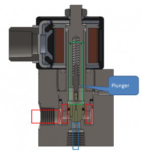
| In Figure 2 the valve is in the closed state, meaning that the piston is completely blocking the orifice. The pilot hole through the center of the piston is also blocked by a pilot pin that is forcibly held down by a compression spring. Fluid pressure exists at the inlet and in all areas highlighted by the red boxes. No power is being delivered to the coil.
The valve shown is a “normally closed” or “fail closed” valve configuration, which means that if the coil is not energized, the valve will be in the closed state. The pressure differential that exists between the inlet and outlet creates a force on the piston and pilot pin as well. Higher pressure differentials equate to higher forces sealing the valve. |
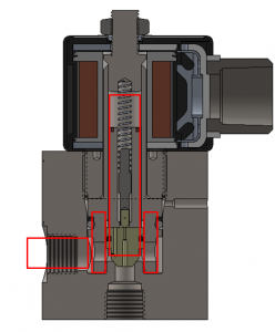
Figure 2 – Closed
|
| Voltage is applied to the coil in Figure 3. The iron-based plunger and pole piece become magnetic, and that force draws them together quickly.
In Figure 3, it is shown that the plunger has moved upward. However, the valve is still closed. |
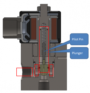
Figure 3 – Plunger initial movement |
|
The coil remains energized in Figure 4. The magnetized plunger has now made contact with the pole piece and has pulled the pilot pin away from the pilot orifice. Fluid has suddenly been allowed to flow through the tiny pilot orifice through the center of the piston. As a result, the pressure has suddenly dropped directly above the piston, represented by the green box. There is now a net upward force on the piston due to different pressures acting on differently sized areas of the piston. |
Figure 4 – Pilot orifice open |
| The net upward force on the piston quickly pops it away from the orifice and fully opens the valve.
Red boxes in Figure 5 represent where pressures are approximately equal to the inlet. A blue box represents downstream pressure, which is slightly less due to flow friction. When the coil is turned off, the plunger and pole piece go back to a non-magnetic state. The compression spring pushes down on the pilot pin, which fully blocks the pilot orifice. A small bleed hole in the side of the piston allows fluid to re-enter above the piston. A net downward force is generated due to the new pressure imbalance and the valve quickly closes. |
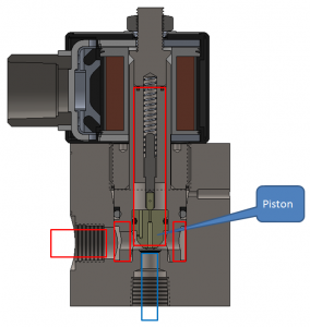
Figure 5 – Piston moved |


