Is the Solenoid Valve Coil Burned Out?

A solenoid valve opens and closes when the proper AC or DC voltage is applied to the coil.  The coil consists of an enamel coated copper wire winding and usually some magnetically permeable metal frame or housing, which may be visible or contained in molding.  There may or may not be a thermal cutoff or fuse in electrical series with the winding.  More complex coils have diode bridges that rectify AC to DC power, and even circuits which can control periodic inrush of current.  The combination of the copper coil, the magnetically permeable surrounding material, and plunger inside the pressure boundary of the valve are collectively known as the “solenoid”.
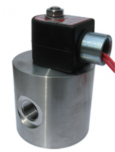
Coil “burn out”, and consequently failure of a solenoid valve to operate, can refer to the following scenarios:

Overheated Copper Wire Enamel

This generally applies to a coil that does NOT have a fuse or thermal cutoff.  If the copper wire, for whatever reason, exceeds the temperature rating by enough to melt away the enamel coating and allow the strands of copper to touch, the number of loops or turns is effectively reduced.  The lower number of turns results in a lower electrical resistance.  The current then increases because the voltage remains constant.  Temperature then exponentially increases as more and more turns are lost and power increases.  Failure occurs when the copper wire or soldered joint melts and breaks the circuit, allowing zero current.  The valve would then return to the “failed” state, i.e. closed if “fail closed”.

Using a solenoid valve in the following scenarios can cause this to happen:

  • Too high of a surrounding ambient temperature for the duration that the coil is held energized
  • A high surrounding ambient and/or high fluid temperature, exceeding catalog ratings.
  • Holding a solenoid energized for long periods of time when it is not rated to be energized indefinitely (continuous duty).
  • Cycling a coil too often in a period of time, which may induce excessive temperatures from inrush current on an AC coil or coil with programmed inrush.
  • In an AC solenoid, a jammed plunger that is prevented from contacting the pole piece will draw more current (near inrush levels). This may over heat the coil.
  • In an AC solenoid, energizing a coil WITHOUT a plunger in the solenoid effectively draws more than the intended current.

Tripped Fuse or Thermal Cutoff

When a coil is built with a fuse or thermal cutoff, the design intent is to prevent surface temperature spikes due to some of the causes listed above already.  One reason for designing these in is to achieve a UL-1203 hazardous location certification and operating temperature code.  The fused coil design can essentially remove all chances of the coil surface ever getting hot enough to ignite a surrounding flammable gas by using fuses.

Different types of fuses are available.  Thermal cutoffs simply sever the circuit when they reach a certain temperature.  Other fuses may trip due to amperage exceeding a certain value.

Since the fuse in embedded in the potting compound or sometimes a welded canister, once tripped, the coil is no longer usable, even after it cools.

Solenoid Valve Coil Conclusion:

Often, a coil is a very simple item to replace on a valve.  However, it is important to understand WHY a coil burned out before simply installing a new one.  For example, if the plunger was jammed inside the valve and a technician simply installed a new coil to replace the burned out one, the new coil would almost surely burn out as well.

Contact your solenoid valve service department whenever you experience a burned out coil.

Solenoid Valves for Methane Emission Reduction

Hydraulic fracturing and horizontal drilling have opened up vast new areas for low-cost natural gas production, and consequently have altered the energy landscape in the United States.  The rush to develop this new resource via new techniques has resulted in numerous environmental challenges, including water and air quality concerns.  Preventable emissions of methane, a potent greenhouse gas with approximately 30 times the heat trapping ability of CO2, are cited by some as among the easiest of those challenges to address.  According to the U.S. Energy Information Administration, marketed production of natural gas increased from approximately 1,650,000 to 2,440,0000 million cubic feet between 2005 and 2017, as in projected to continue the rise.

Methane leaks occur during the production, processing, and transmission of natural gas.  Pneumatic devices, powered by natural gas under pressure, regulate various aspects of the gas passing through them, including temperature, pressure, and flow rate. Many pneumatics are powered by natural gas under high pressure, and vent (or “bleed”) some of that gas to the atmosphere as part of normal operations. High-bleed pneumatic devices are a significant source of methane emissions throughout the supply chain.  According to EPA Inventory data, in 2013, pneumatics emitted roughly 638,000 metric tons of methane, over 20 million metric tons of CO2 equivalent, or a full one-third of all methane emissions from the production sector.  Other studies exist that suggest this might be underestimated by over 40 percent.  Replacing or retrofitting a continuously or intermittently emitting high-bleed controller, defined as emitting an average of over six standard cubic feet (scf) per hour as part of normal operations, can make economic sense.

An alternative solution that eliminates methane emissions altogether is to replace gas-driven pneumatic devices with ones that rely on electricity instead – solenoid actuated valves.  Solenoid valves can be purchased from manufactures such as Clark Cooper configured with certified explosion proof coils per UL-1203 and CSA C22.2 #30.  Stainless steel valves are readily available in sizes 1/2” through 2” with maximum allowable inlet pressures of up to 1500 psi.  Where a power grid is not available, DC coils are available that can be battery operated.  External leakage is essentially zero.  An expensive compressed air system is not required.

How does a Solenoid Valve work?

A solenoid, as it pertains to a valve, is an electromagnetic device consisting of a coil of insulated wire and an iron-based permeable plunger and pole piece.  The following sequence demonstrates how such an arrangement can be utilized to make a plunger work to open or close a valve.  Such is called a “solenoid valve”.


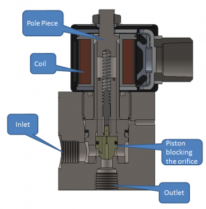
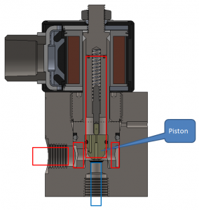
Figure 1 is a section view of a piloted, floating piston, high pressure solenoid valve.  Pressurized fluids enter at the inlet and are held stationary until the piston moves away from the orifice.

A coil is shown surrounding a pole piece outside of the pressure boundary.  The plunger is a free floating piece of permeable steel.


Figure 1 – Nomenclature

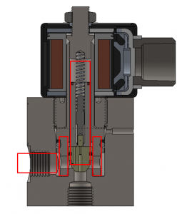
In Figure 2 the valve is in the closed state, meaning that the piston is completely blocking the orifice.  The pilot hole through the center of the piston is also blocked by a pilot pin that is forcibly held down by a compression spring.  Fluid pressure exists at the inlet and in all areas highlighted by the red boxes.  No power is being delivered to the coil.

The valve shown is a “normally closed” or “fail closed” valve configuration, which means that if the coil is not energized, the valve will be in the closed state.

The pressure differential that exists between the inlet and outlet creates a force on the piston and pilot pin as well.  Higher pressure differentials equate to higher forces sealing the valve.

Figure 2 – Closed


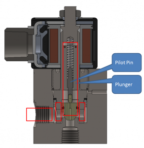
Voltage is applied to the coil in Figure 3.  The iron-based plunger and pole piece become magnetic, and that force draws them together quickly.

In Figure 3, it is shown that the plunger has moved upward.  However, the valve is still closed.

Figure 3 – Plunger initial movement


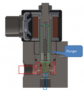
The coil remains energized in Figure 4.  The magnetized plunger has now made contact with the pole piece and has pulled the pilot pin away from the pilot orifice.

Fluid has suddenly been allowed to flow through the tiny pilot orifice through the center of the piston.  As a result, the pressure has suddenly dropped directly above the piston, represented by the green box.

There is now a net upward force on the piston due to different pressures acting on differently sized areas of the piston.


Figure 4 – Pilot orifice open

The net upward force on the piston quickly pops it away from the orifice and fully opens the valve.

Red boxes in Figure 5 represent where pressures are approximately equal to the inlet.

A blue box represents downstream pressure, which is slightly less due to flow friction.

When the coil is turned off, the plunger and pole piece go back to a non-magnetic state.  The compression spring pushes down on the pilot pin, which fully blocks the pilot orifice.  A small bleed hole in the side of the piston allows fluid to re-enter above the piston.  A net downward force is generated due to the new pressure imbalance and the valve quickly closes.

Figure 5 – Piston moved

Valve Body Connections for High Pressure Solenoid Valves

NPT

NPT American National Standard Taper Pipe Threads per ANSI/ASME B1.20.1 are commonly used on high pressure solenoid valves.  The maximum allowable pressure is dependent on size and connector material, but can be as high as 10,000 psi.  It is therefore always prudent to investigate pressure capacities with the component manufacturers.

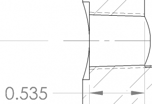
Picture 1 – ¼” NPT

Female NPT threads are created in valve bodies by tapping, single point turning, or thread milling.  Unlike the SAE J1926 and Medium Pressure Connection, sealing is not created on interfacing smooth cone faces, but rather on the threads themselves.  In order to provide good sealing across multiple brands of connectors, female connections should not only meet the “L1” gage distance per ASME B1.20.1, but also provide an adequate number of full threads past the hand tight engagement length.

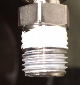
Application of a thread sealant is mandatory in order to block the spiral path between the peaks and valleys of the male and female interface of ASME B1.20.1 NPT threads. Three to four wraps of PTFE tape is preferred over liquid sealants.  This is because overuse of a liquid may cause drippage into operationally sensitive areas of the solenoid valve.  Picture 2 is an example of how properly applied PTFE tape will look after a connector is removed from quality threads that have been fully tightened.  The white tape is evenly compressed across the faces and valleys.  One indication of improperly machined threads or inadequate length of engagement would be a thick string of PTFE nestled in the thread valley.  This is one clue that the components did not (or could not) compress together fully.

Picture 2 – Good application of PTFE tape

Installation torques are not commonly published for NPT connections.  It is somewhat of a trial and error system to get them to seal by keeping track of the angle of rotation past hand tight.  Reversing the connector out will ruin the sealant and will require the installer to re-apply.  Consult the specification for the number of threads that should engage, hand tight, for a given NPT size.

NPT is the easiest connection to manufacture, and is sufficient for the bulk of solenoid valve applications.  However, once an assembler gets the connection to seal, there is very limited flexibility on the angle of rotation to which it must connect to other things (e.g. piping, tubing, etc.) unless accommodations are made via adjustable tube connectors.  There are also minor nuances between connectors from different manufactures.

SAE J1926

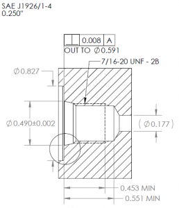
Connections per SAE J1926/1 utilize straight ISO 725 threads (inch) and a smooth 12 or 15 degree sealing cone interface.  The male SAE connector has an o-ring of chosen material that seals on the female cone.  The specification states a maximum allowable pressure of 63 MPa [9135 psi] for connections put together with nonadjustable stud ends, but always be sure to check with the component manufacturers.

As seen in Picture 3, the SAE connection is somewhat more elaborate than the NPT.  For a comparable inner diameter through which fluid can flow, the connection tends to need more axial length in order to fit it into the valve body.

Picture 3 – SAE J1926-1 Size ‘-4’ Connection

From our experience at Clark Cooper it is easier to make a perfect seal with SAE connectors as compared to NPT.  Installation torques are readily accessible for SAE.  However, an end user must take the o-ring material selection into account to ensure compatibility with the fluid type and temperature.  The SAE connection is generally not used for cryogenic applications due to that o-ring.

MPF

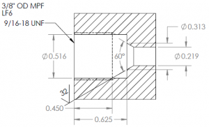
The 20,000 psi “Medium Pressure Fitting” (MPF) connection utilizes inch-based standard thread and a 60 degree cone at the base of that thread.  All sealing is accomplished on the metal-to- metal cones without the use of an o-ring or thread sealant.  This versatile connection, despite not requiring an elastomeric o-ring, can still perfectly seal high pressure gases such as hydrogen and helium.

Care must be taken during machining to ensure a smooth cone.  Cleanliness is important as well during installation.

Picture 4 – LF6 Medium Pressure Connection