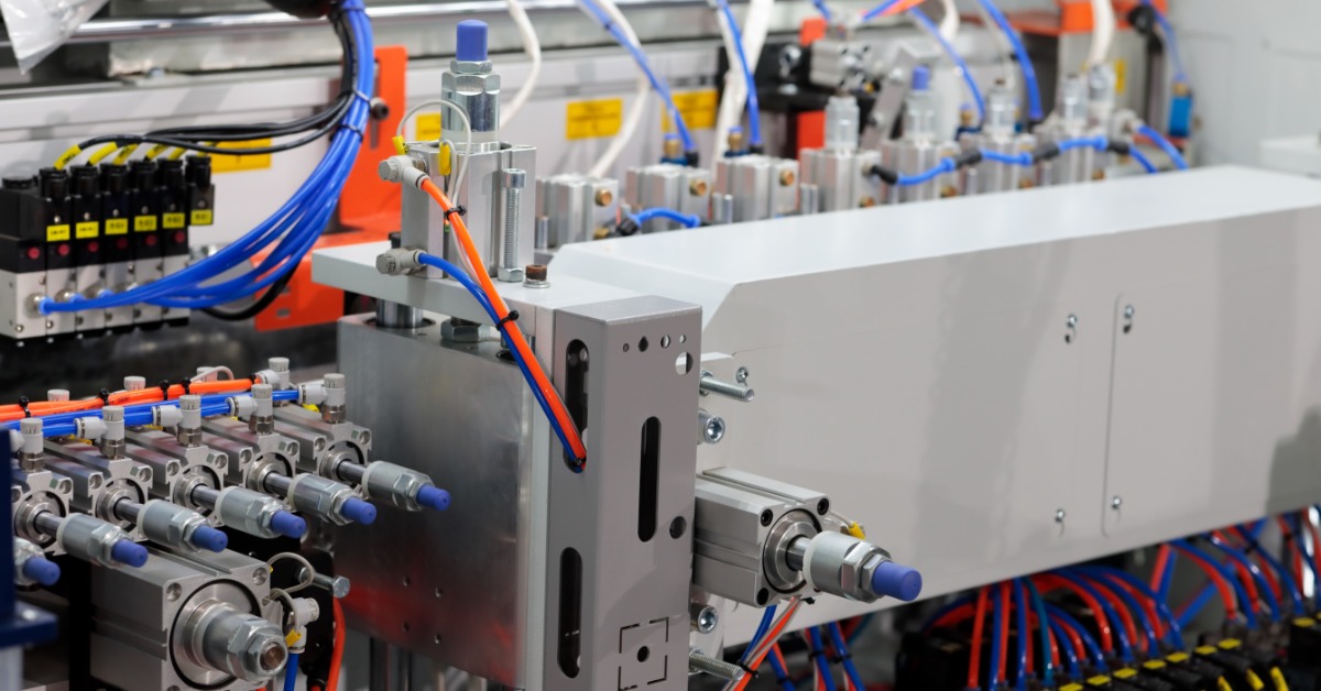
Solenoid valves help systems control the flow of fluids or gases with an electrical signal. When a valve fails to open or close at the right time, the larger system can lose pressure control. A thorough test process helps maintenance teams identify the source of the problem before replacing parts that still work. Here are the steps for testing a solenoid valve.
Step 1: Confirm the Valve Information
Start by checking the valve nameplate or product documentation. The voltage rating shows how much power the coil needs to operate correctly. The pressure rating helps confirm whether the valve fits the system conditions, while the valve type explains how the valve should respond during testing.
Reviewing the valve information gives the test process a clear starting point. When a technician uses the wrong specifications, the test can point in the wrong direction. The wrong voltage can make a working valve appear faulty or mask the real issue elsewhere in the system.
Step 2: Shut Down the System Safely
Before testing begins, make sure the valve area is safe to handle. Turn off the power source and follow the site lockout process before working near electrical connections. Relieve line pressure before loosening fittings or removing the valve from service.
A solenoid valve can remain under pressure after the equipment stops running, so give the system time to settle before opening any part of the line. This extra precaution helps protect the technician and keeps the inspection process controlled from the start.
Step 3: Inspect the Valve Body and Coil
Look over the valve body for damage, then check the connection points for signs of leakage. If the coil housing shows cracks or heat marks, the valve may have an electrical issue that needs attention before testing continues.
Give the wiring the same careful review because loose leads can interrupt power to the coil. A damaged connector can make the valve appear to have failed, even when the internal parts still work. This early inspection helps narrow the issue before you begin taking measurements.
Step 4: Check the Electrical Supply
Use a multimeter to confirm that the supply voltage matches the rating on the coil. When the voltage falls outside that range, the coil may not have enough force to move the plunger correctly. This reading helps you decide whether the issue starts with the valve or with the power feeding it.
A weak supply can make the valve chatter or respond slowly, even when the valve itself can still function. Check the control circuit before replacing the valve so the repair matches the actual problem. That extra step can prevent an unnecessary replacement and keep the troubleshooting process focused.
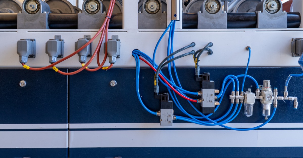
Step 5: Measure Coil Resistance
Another step in testing a solenoid valve is listening for it to actuate. Restore power only when the valve area is ready for a live test. As the valve energizes, a firm click from the coil area can show that the coil has moved the plunger.
A missing click gives you a reason to keep troubleshooting, not a reason to replace the valve right away. The coil may not receive the correct voltage, or buildup may restrict plunger movement. Compare what you hear with the voltage reading so the test points to the real issue.
Step 6: Listen for Actuation
Restore power only when the valve area is ready for a live test. As the valve energizes, listen for a firm click from the coil area. That sound indicates the coil has generated enough force to move the plunger.
If you do not hear a click, keep troubleshooting before you blame the valve. The coil may not receive the right voltage, or buildup may keep the plunger from moving freely. Compare what you hear with the voltage reading so that the test points to the real issue.
Step 7: Watch the Valve Response
Watch how the valve responds when the control signal changes. The valve should shift cleanly into the correct position for its design, then hold that position without delay. If the system does not show the expected change in flow, compare the response with the valve type before moving to the next test.
A slow or uneven response can point to a problem inside the valve. Dirt may restrict movement, or the coil may not create enough force to shift the plunger. If the valve changes position but still leaks, the seat may need closer inspection.
Step 8: Review Pressure Conditions
A valve may test well on the bench but struggle under real pressure. Check the inlet pressure against the valve rating before judging performance. If the design depends on pressure assistance, confirm that the system provides enough pressure differential for proper operation.
Pressure problems can look like valve failure because the system response may change in a similar way. Excess pressure can keep internal parts from moving as intended. Low pressure can also reduce the force needed for the valve to shift during operation.
Step 9: Check for Debris Inside the Valve
If the electrical checks look normal, inspect the internal flow path next, provided the manufacturer allows service. Debris near the seat can keep the valve from sealing correctly, while buildup around the plunger can interfere with smooth movement during operation. A clean internal path helps the valve respond the way the electrical test suggests it should.
Handle the internal inspection carefully, as small parts require proper placement during reassembly. Follow the valve documentation closely so the plunger moves freely after inspection. Contact the manufacturer before opening a custom-designed valve.
Step 10: Test the Valve Under Real Operating Conditions
A final test should show how the valve performs in the actual system. Run the normal operating sequence and watch the valve response as the control signal changes. The valve should move cleanly without chatter or delayed action.
Real operating conditions can reveal problems that a simple bench test may miss. Temperature changes can affect coil heat, while pressure changes can affect movement inside the valve. When the valve performs well during this final check, the team can return the equipment to service with more confidence.
Know When To Replace the Valve
A failed test does not always mean the valve needs replacement. If the test indicates a wiring issue, an electrical repair may resolve the problem. If debris prevents normal movement, careful cleaning may restore valve function.
Use the test results to decide whether repair or replacement makes more sense. Replace the coil when testing confirms a coil failure, but consider a full valve replacement if internal wear prevents a tight seal after cleaning. A properly matched replacement helps protect the larger system from repeat trouble.
Work With Clark Cooper for Solenoid Valve Support
Testing works best when technicians understand both the electrical and mechanical sides of the valve. Clark Cooper is a solenoid valve manufacturer that makes reliable valves that work for demanding applications. A careful process helps teams avoid unnecessary replacement while keeping critical systems running as intended.
Leave a Reply