Solenoid Valve Certifications: What is CRN Certification?

CRN

CRN is an acronym for Canadian Registration Number, which is assigned by each province or territory of Canada to accept and register the design of a boiler, pressure vessel, or fitting.  The numbers after the decimal place in the CRN represent different provinces or territories as follows:

1 = British Columbia
2 = Alberta
3 = Saskatchewan
4 = Manitoba
5 = Ontario
6 = Quebec
7 = New Brunswick
8 = Nova Scotia
9 = Prince Edward Island
0 = Newfoundland
N = Nunavut
T = Northwest Territories
Y = Yukon Territory Purpose

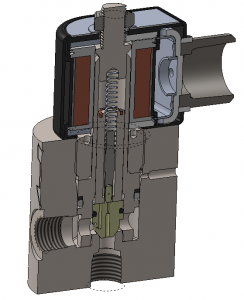
A solenoid valve, for example, will be registered as a Type ‘C’ fitting.  The manufacturer would submit and demonstrate compliance to pertinent design standards, such as the ASME Boiler & Pressure Vessel Code via calculations, drawings, test data, etc.  A manufacturer must present proof of being regulated by a Quality Control Program such as ISO 9001 that is audited by a reputable authority.

The overall intent of the CRN is to give the end user peace of mind that the product is well designed and safe.  The vast majority of Clark Cooper Valves, for example, come with CRN approval.

UL-429

UL-429 is the Standard for Safety for Electrically Operated Valves. It includes requirements for various types of valves, such as valves for general purpose, hazardous fluids and designated safety.  A manufacturer must submit component drawings for the valves undergoing certifications, as well as the fluid type, fluid temperature range, and ambient temperature range for which the certification is to apply.

All valves must operate with fully heated components using 10% over nominal voltage, and just 85% of rated voltage.  External leakage, seat leakage and endurance tests potentially up to 100,000 cycles are included.

A certification to UL-429 provides an end user with 3rd party verification that a valve design was scrutinized rigorously through actual testing.

UL-1203

UL-1203 is the Standard for Safety for Explosion-Proof and Dust-Ignition-Proof Electrical Equipment for Use in Hazardous Locations and applies to the U.S.  In terms of equipment certification for hazardous location and explosion atmospheres, it defines the rules for a “protection type”.  One can view the Class, Division, Group, and temperature class description by downloading a guide summary.

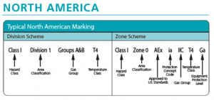
Using the guide, the certification code can be broken so that an end user fully understands:

  • What gases can be safely used around the equipment
  • How often those flammable gases are present
  • The allowable surrounding ambient air temperature range
  • The maximum surface temperature that the equipment may reach

For example, a company may advertise “Explosion-Proof” per UL-1203, Class I, Division 1, Groups A through D hazardous locations with operating temperature code, “T2D”, for an ambient temperature range of -20 to +85 C.  Class 1 refers to flammable gases.  Groups A through D include certain gases such as hydrogen and acetylene.  T2D means that the surface temperature of the equipment will not exceed 215 C [419°F] in 85 C surrounding air.

CSA C22.2 #139

The CSA group, Canadian Standards Association, issued CSA C22.2 #139 as essentially the Canadian version of UL-429.  Like UL-429, a certification to this standard provides the end user with 3rd party verification that a valve design was scrutinized rigorously through actual testing.  It includes similar temperature, operation, endurance and leakage tests as UL-429.

ATEX

ATEX Certification of a solenoid valve implies conformity to European Directive 2014/34/EU for potentially explosive atmospheres per BS EN 60079-0 and 60079-1.  It is the European version of UL-1203, and similarly uses a code scheme.

The ATEX code will include equipment group and category, atmosphere group, protection type, and temperature class for a given ambient and fluid temperature range.

Certain valves manufactured by Clark Cooper are available with ATEX coils as well.

The Main Uses of Solenoid Valves and the Industries that Use Them

What Solenoid Valves Do

Solenoid valves are an advantageous solution for controlling the flow of many liquids and gases of a huge temperature range where either an “on” or “off” state is needed.  A piston that may contain a metal or soft disk either covers or moves away from an internal orifice separating the inlet from outlet.  When the piston is blocking the orifice, a pressurized fluid is held stationary at the inlet and up into the bonnet tube.  A differential pressure exists over the orifice area, for which the resultant force combines with any downward spring force to create a tight seal.  Upon energization of a solenoid, internal components move in various ways that result in the piston either moving away from or towards that orifice to open or close the valve.  If the valve was a “proportional” solenoid valve, essentially infinite positions of that piston could be created by varying the supply voltage to create a throttling effect. oriffice

Simple Setup

Solenoid valves are easy to install.  Many simply have two lead wires connected to a coil nested around a bonnet tube containing materials that easily magnetize and demagnetize.  Either wire can be line voltage.  Switches or relays can be designed into the control system to route power when needed to quickly open or close the solenoid valves.  Selection of a solenoid valve can eliminate the need for long and expensive air lines and air delivery systems that would be needed for pneumatically actuated valves.  For long wire runs on remote locations, higher AC voltages may be utilized to minimize power loss.  For example, 240V AC is commonly sold.

Voltages

Solenoid coils are offered in many voltages, typically 12, 24, 120, 240V DC, and 24, 120, and 240V AC, which suit the majority of applications. Coils are easily developed for less common voltages as well. While the valve may be designed to achieve catalog pressures assuming the nominal voltage, the valve may still operate effectively at voltages lower than those nominal values.  This feature is ideal for battery powered systems that may provide lower voltage over time.  An AC coil will generally run hotter than a DC coil wound for the same power output due to hysteresis characteristics of the magnetic circuit.  An AC coil will also have an initially high “inrush” of current on the order of 2-10 times the nominal steady state current.  A system designer should be aware of inrush amperage and heat outputs, along with the resulting coil surface temperatures.  These temperatures are dependent upon the duty cycle of the valve, which includes energization frequency and the duration held energized, along with ambient and fluid temperatures.  While it may take several hours for a coil to reach steady state surface temperatures, the majority of the temperature rise would be noticeable in the first hour.

Hazardous Locations and Explosive Atmospheres

Solenoid valves can be configured with certified explosion proof coils per UL-1203, CSA C22.2#30, and ATEX.  The copper coil wire may be encapsulated and isolated from any flammable gases that may be continuously present outside of the valve.  Flame proof designs consist of somewhat of a labyrinth so that even if flammable gas was ignited inside the coil, it would not propagate and ignite gas surrounding the valve.  For situations where flammable gases may be continuously present, electric motors are often not permitted due to sparking.  Taking this a step further, “intrinsically” safe coils with power outputs so low that they cannot ignite a gas may also be selected as well.  These, however, have very limited opening force due to such low power.  Industries concerned with flame propagation typically deal with natural gas processing and transportation, hydrogen refueling and fuel cells, methane recovery, and oil and gas in general.

Speed

Time to open and close is extremely fast on solenoid valves, and is often on the order of 50-300 milliseconds.  The smaller the valve, the quicker the small internal components can be made to move over short distances.  On piloted valves with larger traveling distances, viscous liquids tend the have the effect of slowing the movements down as internal components must push through those fluids.  Applications requiring a fast response time need look no further than solenoid valves.

Packless

Motor controlled valves and ball valves often have a stem that punctures the pressure boundary of the valve.  This stem is surrounded by a tight packing, often PTFE or graphite, to seal the high pressure fluid.  The packing may wear over time, and such wear may be exacerbated by shifting temperatures and ingress of contaminants.  Solenoid valves often have one motionless seam where the bonnet attaches to the valve body.  A gasket or o-ring of a material compatible with the working fluid can reliably be selected for this seam.  Radioactive applications sometimes do not allow the use of elastomeric gasket materials, so bonnets are welded to valve bodies.  Industries focused on minimizing fugitive emissions to reduce air pollution may opt for a packless solenoid valve.